STP is a Layer 2 link management protocol that provides path redundancy while preventing loops in the network. For a Layer 2 network to function properly, only one active path can exist between any two stations. Spanning-tree operation is transparent to end stations, which cannot detect whether they are connected to a single LAN segment or to a LAN of multiple segments.
Spanning Tree Protocol (STP) is used to make a loop free network by monitoring the network to track all the links and shut down the least redundant ones.
Types of Spanning Tree Protocol (STP) –

PVST+ is the default configuration of IEEE 802.1D on Cisco switches. It runs one instance of STP for each VLAN. A newer, faster-converging spanning-tree protocol, RSTP, can be implemented on Cisco switches on a per-VLAN basis in the form of Rapid PVST+. Multiple Spanning Tree (MST) is the Cisco implementation of Multiple Spanning Tree Protocol (MSTP), where one instance of spanning tree runs for a defined group of VLANs.
Features such as PortFast and BPDU guard ensure that hosts in the switched environment are provided immediate access to the network without interfering with spanning-tree operation.
Switch stacking allows connection of up to nine Catalyst 3750 switches to be configured and presented to the network as a single entity. STP views the switch stack as a single switch. This additional benefit helps ensure the IEEE recommended maximum diameter of seven switches.
In a LAN, redundant links are added to improve the network availability of LAN. But this redundant links may cause frame to loop in the network for infinite time until some action is taken, e.g, some links are taken down. To cope with problem of frame looping, Spanning Tree Protocol (STP) comes into play.
Need for Spanning Tree :
Consider the scenario below with 3 switches with one user attached to each switch.
Arvind sends a broadcast frame to LAN and as nature of switch frame are send out from other ports (Gi0/1 & Gi0/2) except receiving port (Fa0/3). Now, this frame goes to SW2, SW2 also broadcast frame out of Gi0/2 and Fa0/2 ports. SW1 receives frame in its Gi0/1 ports. SW1 also broadcast frame then this frame goes to SW3 and frame broadcasting goes on. Remember that this frame broadcast also occurs in other direction from SW3 out of Gi0/1 port. Above discussed frame looping was from SW3’s Gi0/2 ports. You can imagine the frame flooding in that small LAN. This forever looping of frames around LAN is called Broadcast storm.
This Looping of frames causes three problems as stated below:
1) MAC table instability –
Due to looping of frame around LAN, MAC-Table of switch get changed frequently. Looping causes incorrect MAC-table entries resulting in incorrect frame delivery.2) Broadcast Storm –
Repeated forwarding of frames around links in LAN causes the inefficient use of links.3) Multiple Frame Transmission –
A very serious negative effect of looping is that multiple copies of same frame are delivered to host. This process left host with confusion.How Spanning Tree Protocol helps ?
Spanning tree protocol prevent looping of frames around LAN by placing ports of switch in either forwarding or blocking state. Interfaces (ports of switch) which are in forwarding state act as normally but Interfaces in blocking state doesn’t process any frame received except STP messages and other important overheads. Blocking Interfaces doesn’t learn MAC addresses, don’t forward frames and don’t process received frames.
Now if we again consider the above discussed scenario with SW3’s Gi0/2 interface in blocking state.

SW3 forwards frame only to Gi0/1 port as Gi0/2 port is in blocking state.
Now SW1 receives frame and forward to Fa0/1 and Gi0/1 interfaces.
SW2 receives frame and forward to Fa0/2 and Gi0/1 interfaces.
SW3 will receive the frame on Gi0/2 interface but ignores the frame as it is in blocking state.
In this way looping of frame around LAN can be prevented by using STP.
These are some important terms related to Spanning Tree Protocol:
Bridge Priority Data Unit (BPDU) – It contains the Bridge I’d, Sender’s Bridge I’d, Cost to the Root Bridge, Timer values on Root Bridge. All switches exchange BPDU in order to elect root bridge. The switch with the lowest Bridge I’d will become the root bridge.
Bridge I’d – It is a 8-byte field which is a combination of bridge priority (2 bytes) and Base Mac address (6 bytes) of a device. If there is a tie on bridge priority then the Base Mac address is considered.
Bridge Priority – It is priority, which is assigned to every switch, 32768 by default.
Root Bridge – The root bridge is the bridge with lowest Bridge I’d. All the decisions like which ports are the root ports (the port with best path to the root bridge) are made from the perspective of root bridge.
Path cost – A switch may encounter one or more switch in the path to the root bridge. All the paths are analysed and the path with the lowest cost will be selected.

Root port –A root port is selected on all non-root bridge switches on a per-switch basis. Root ports are the switch ports closest to the root bridge, based on the overall cost to the root bridge. There can be only one root port per non-root switch. Root ports could be single-link interfaces or an EtherChannel port channel interface.
Designated port – A designated port is a non-root port that is permitted to forward traffic. Designated ports are selected on a per-segment basis, based on the cost of each port on either side of the segment and the total cost calculated by STP for that port to get back to the root bridge. If one end of a segment is a root port, then the other end is a designated port. All ports on the root bridge are designated ports.
Alternate port and backup port—An alternate port and a backup port are in a blocking state (or discarding state) to prevent loops. Alternate ports are selected only on links where neither end is a root port. Only one end of the segment is blocked, while the other end remains in forwarding state, allowing for a faster transition to the forwarding state when necessary.
Disabled ports—A disabled port is a switch port that is shut down.
NOTE- The port roles displayed are those defined by RSTP. The role originally defined by the 802.1D STP for alternate and backup ports was non-designated.
Root Bridge election
All the switches in the network declare themselves root bridge and start exchanging their own BPDU. The BPDU with the lowest bridge I’d will be considered as superior. Now the switch receiving the superior BPDU make changes in its own BPDU and carry forward to its neighbours. It changes the value of root Bridge I’d with its superior BPDU bridge I’d. This process goes on until all the switches are satisfied with which bridge have the lowest bridge I’d and hence that switch will be declared as root bridge.
Now according to the criteria, the root ports will be selected and then the port left will be in blocking mode.
Criteria for selecting root port:
Spanning Tree Root Port selection process in a Non-Root Switch involves the following steps.
1) Select the port connected to the path with the lowest accumulated Spanning Tree Path Cost to the Root Bridge (Root Switch) as the Root Port, when a Non-Root Switch has multiple paths to reach the Root Switch.
2) If multiple paths are available to reach the Root Bridge (Root Switch) with the same accumulated Spanning Tree Path Cost in a Non-Root Switch, select the port connected to the neighbor switch which has the lowest Switch ID value as the Root Port.
3) If all the multiple paths go through the same neighboring switch to reach the Root Bridge (Root Switch), Non-Root Switch will select the local port which receives the lowest port Spanning Tree Port Priority value from neighbor Switch as the Root Port.
4) If the received Spanning Tree Port Priority value values are the same between the connecting ports to reach the Root Bridge (Root Switch), Non-Root Switch will select the port which receives the lowest physical port number from neighbor Switch as the Root Port. This is the last tie breaker.
Consider Following Example-
1) Select the port connected to the path with the lowest accumulated Spanning Tree Path Cost to the Root Bridge (Root Switch) as the Root Port, when a Non-Root Switch has multiple paths to reach the Root Switch.

Above topology,SW4 has two paths to reach the Root Switch (SW1). Total Spanning Tree Path Cost to reach the Root Switch (W1) via left path is 19+4 = 23 (19 is the Spanning Tree Cost for Fast Ethernet Link and 4 is the Spanning Tree Cost for Gigabit Ethernet Link) and the total Spanning Tree Path Cost to reach the Root Switch (Switch 1) via right path is 4+4 = 8 (4 is the Spanning Tree Cost for Gigabit Ethernet Link).
Therefore SW4 will select the port with least Spanning Tree Path Cost to reach the Root Switch (SW1) as its Root Port (which is marked as RP in SW4 in above diagram).
2. If multiple paths are available to reach the Root Bridge (Root Switch) with the same accumulated Spanning Tree Path Cost in a Non-Root Switch, select the port connected to the neighbor switch which has the lowest Switch ID value as the Root Port.

Above topology, SW4 has two paths to reach the Root Switch (SW1). Total Spanning Tree Path Cost to reach the Root Switch (SW1) via left path is 4+4 = 8 (4 is the Spanning Tree Cost for Gigabit Ethernet Link) and the total Spanning Tree Path Cost to reach the Root Switch (SW1) via right path is 4+4 = 8 (4 is the Spanning Tree Cost for Gigabit Ethernet Link).
Above topology, both path has the same accumulated Spanning Tree Path Cost to reach the Root Switch (SW1). Now the SW4 will select the port connected to the Switch which has the lowest Spanning Tree Switch ID, as the Root Port. As shown in above topology, out of the two neighbour switches that can be used to reach the Root Bridge, SW2 has the MAC address 0000:0000:0002 and SW3 has the MAC address 0000:0000:0003.
Above topology, SW2 has the lowest MAC address (0000:0000:0002) and SW4 will select the port connected to SW2 as the Root Port (which is marked as RP in SW4 in above diagram).
3. If all the multiple paths go through the same neighboring switch to reach the Root Bridge (Root Switch), Non-Root Switch will select the local port which receives the lowest port Spanning Tree Port Priority value from neighbor Switch as the Root Port.
Consider the situation where multiple paths are available to reach the Root Bridge (Root Switch) with the same accumulated Spanning Tree Path Cost, and all paths go through the same neighbor switch to reach the Root Bridge. Now both the cases mentioned above are tie.
In this case, Spanning Tree Protocol will choose the local port which recieves the BPDU with lowest Spanning Tree Port Priority value from the neighbour switch as the Root Port. Default Spanning Tree Port Priority value value is 128 and you may change the Port Priority value in increments of 16.

Above topology, SW5 has two paths with the same accumulated Spanning Tree Path Cost to reach the Root Switch (SW1) and both paths are are connected via SW4.
Fa0/24 port in SW4 is configured with a Spanning Tree Port Priority value of 16. omnisecu.com.SW5 will select its local port fa0/24 as the Root Port (which is marked as RP in SW5), because fa0/24 is the port which recieves the BPDU with lowest Spanning Tree Port Priority value from the neighbour switch SW4.
4. If the received Spanning Tree Port Priority value values are the same between the connecting ports to reach the Root Bridge (Root Switch), Non-Root Switch will select the port which receives the lowest physical port number from neighbor Switch as the Root Port.
Consider the situation where multiple paths are available to reach the Root Bridge (Root Switch) with the same accumulated Spanning Tree Path Cost, and all paths go through the same neighbor switch to reach the Root Bridge. All the ports in the neighbour switch are configured with the same Spanning Tree Port Priority value. Now all the cases mentioned above are tie.
In this case, Spanning Tree Protocol will choose the port on the local switch, which recieves the BPDU with lowest physical port number from the neighbour switch as the Root Port. For example, on a 2960, that would be FastEthernet 0/1 or Gigabit 0/1.

Above topology, SW5 has two paths with the same accumulated Spanning Tree Path Cost to reach the Root Switch (SW1) and both paths are are connected via Switch 4. Both fa0/23 and fa0/24 ports are connected to fa0/23 and fa0/24 ports on SW4, which has the same Spanning Tree Port Priority value.
Now SW5 will select fa0/23 as the Root Port (which is marked as RP in SW5), because fa0/23 is the port on SW5, which recieves the BPDU with lowest physical port number from the neighbour switch, SW4. This is the last tie breaker.
Same can be seen in a small topoloies ( The situation where there is tie as the both link from sw2 are going via SW1 to root bridge SW0, so the port no Fa0/1 ( between Fa0/1 and Fa0/2) will become the root port) -

Designated Port Selection-
Spanning Tree Designated Port Selection is almost same as Spanning Tree Root Port selection.
After selecting the Spanning Tree Root Ports (best port to reach the Root Bridge), Spanning Tree Protocol will make the other end of the Root Port connecting to the next Switch as Designated Port.
Every Switch has only one Spanning Tree Root Port (best port to reach the Root Switch (Root Bridge)). For any other network segments in a Switch which does not include a Root Port, Spanning Tree will select one port as Desingated Port and other as Non-Designaged Port. For that segment, Designated Port will be in Spanning Tree Forwarding State and Spanning Tree Non-Designated port will be in Spanning Tree Blocking State.
Root Port is the port on any Non-Root Bridge which is the best port to reach the Root Switch (Root Bridge). Hence, there is no Root Port in Root Bridge. All the ports in a Root Switch (Root Bridge) are Spanning Tree Designated Ports and will be in Spanning Tree Forwarding State.
Following are the different steps for selecting the Spanning Tree Designated Port.
• Select the port on the Switch on the network segment (which does not include a Root Port) with the lowest accumulated Spanning Tree Path Cost to the Spanning Root Bridge (Root Switch) as the Designated Port and other side of the Designated Port will be the Non-Designated Port.
• If there is a tie in accumulated Path Costs between the two switches in the network segment, then select the port on the switch with the lowest Spanning Tree Switch ID as the Designated Port and other side of the Designated Port as the Non-Designated Port.

Above topology, the ports marked with "RP" are Spanning Tree Root Ports, the ports marked with "DP" are Designated Ports and the ports marked with "NDP" are Non-Designated Ports. We can see that there is no Spanning Tree Root Port for the network segment between SW3 and SW4. The port on the Switch which has better Spanning Tree Path Cost (SW3) is selected as the Designated port and other end of the Designated Port is the Non-Designated Port.
Spanning Tree Root Port and Spanning TreeSpanning Tree Designated Port will be in Spanning Tree Forwarding State and Non-Designated Port will be in Spanning Tree Blocking State.
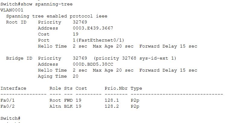
Command to Check Spanning tree -
By default, Cisco Switches are running a mode of Spanning Tree Protocol, known as Per-VLAN Spanning Tree Protocol + (PVST+). PVST+ is based on the IEEE 802.1D standard, added with Cisco proprietary extensions. The PVST+ runs on each VLAN on the switch, which means that there is a separate Spanning Tree Protocol instance for each VLAN.
The 16-bit Bridge Priority (Switch Priority) Value included in the BPDU's must hold both the Bridge Priority (Switch Priority) Value and the VLAN information, as shown below. The VLAN information is added as 12-bit Extended System ID .
Hence the Bridge Priority (Switch Priority) Value 32769 from the output of show command "show spanning-tree" is the sum of default Bridge Priority (Switch Priority) Value 32768 and the VLAN number, 1 (In below example, we have only one VLAN).
At Root Bridge

At Non Root Bridge 1

At Non Root Bridge with Blocking Port
Command to change bridge ID priority value

Command to change port priority value

Command to change port priority value

STP Timers
Hello Timer – This is how often the root bridge will send out BPDUs. These BPDUs get relayed down the spanning-tree to all the other switches. The default is 2 seconds.
Max Age Timer – This is how often a bridge will actually save the BPDU information it receives from other switches. Think of it as sort of a hold timer. The default is 20 seconds, and it helps prevent against loops in the event of indirect link failures.
Forward-Delay — This determines how long a switch will spend in each of the listening and learning states of STP. The default is 15 seconds, which means that out of the box we spend 15 seconds in listening and 15 seconds in learning.
Common STP Timers:
Hello time = 2 secsMax Age = 20 secs
Listening = 15 secs
Learning = 15 secs
Total time = 50-52 secs to convergence
The different states of STP are as follows:STP States
Blocking — In the blocking state the port is essentially shut down. The switch discards frames received on the interface. It will receive BPDUs from the DP on the segment but will not pass them along to other switches. The important thing to note, and that we will see in this blog through actual logs is that the blocking state is not something that a port goes into every single time it comes up. A switch will go through the blocking state when it is first initialized (boots up) and it will place ports that could cause L2 loops into blocking when necessary. This does not mean that every single time you plug a device into the switch that the port goes into blocking before going to listening and learning. As we will see later, the blocking state is typically only seen during indirect link failures.
Listening —In listening state the port is starting to transition into doing something. In this state, the switch will actually process the BPDUs it receives on the port although we are still discarding frames at this point. Note that per the RFC Listening and Learning MUST be the same amount of time. There is no way to tweak one or the other. If you change one, you change the other.
Learning — In the learning state the port continues it’s transition by learning MAC addresses on the port, continuing to receive and process BPDUs, and transmitting BPDUs on to neighboring switches. Note that per the RFC Listening and Learning MUST be the same amount of time. There is no way to tweak one or the other. If you change one, you change the other.
Forwarding — In the forwarding state the port is up and running. At this point the port actually forwards frames and continues to monitor BPDUs
Disabled — This isn't really a state of STP. This means STP is essentially turned off.


The beauty of this algorithm is, STP could automatically calculate a loop free topology for our network, but there are several drawbacks for calculating:
1. The max_age timer: if topology changed, an indirect block port will wait for its “max_age” expires to enable it to listening state, by default, it will wait @ 20 secs on cisco switches.
2. Accesses ports do not need to participate in STP calculating, because it directly connected to end-devices.
3. Even the STP radius is smaller than default (7 switches), the STP port will wait a whole rtt time to proceed to forwarding state ( 15sec for sending, 15 secs for receiving) no feedback solution
Because of above reasons, we need to wait at least 52 secs to re-converge into a new STP network, which is totally unendurable for some critical business env. So a btr version 802.1W RSTP.
But before moving to the RSTP , we must know the before the industry standard was ratified means RSTP and other protocol comes in picture , then CISCO provide some alternative i.e.-
1) PortFast
2) BPDUGuard
3) BPDUFilter
4) UplinkFast
5) BackboneFast
If you have a laptop or a server connected to a switchport then you know that:
-It will not need to listen to BPDUs because it is not a layer 2 device
-It will not create loops because it has a single link to the layer 2 network
Therefore, you can safely disable Spanning Tree on such ports. It is very important to ensure that such ports never have a STP enabled layer 2 device connected on them (Think port security!) or else a loop or a breakdown of the network is quite possible. You will even get a warning message on certain switches stating this when you enable portfast on a switchport!
When you configure a switchport as portfast, STP will be disabled on that port and it will transition to forwarding state when it comes up and will never be blocked.
The command to configure portfast is spanning-tree portfast:

As we learned, Portfast disables STP on a switchport but an important fact is that a Portfast switchport will keep listening for BDPUs. If someone adds a switch to a port which has been configu as Portfast, the consequences will be unpredictable and is some cases disasterous.
To guard against this situation, Cisco provides the BPDUGuard and BPDUFilter features.
If a switch is plugged into a switchport configured as Portfast, it could change the STP topology without the administrator knowing and could even bring down the network. To prevent this, BPDUGuard can be configured on the switchport. With this configured, if a BPDU is received on a switchport, it will be put into an error disabled mode and an administrator will have to bring the port up. This can be configured on the port using the “spanning-tree bpduguard enable” command.
When BPDUFilter is configured on a switchport which has been configured as Portfast, it will cause the port to lose the Portfast status if a BPDU is received on it. This will force the port to participate in STP convergence. This is unlike the behavior seen with BPDUGuard where the port is put into an error disabled mode. BPDUFilter can be enabled on the switchport using the “spanning-tree bpdufilter enable” command.
If a switch has multiple links towards the root bridge, then UplinkFast marks the redundant link as an Alternate Port and brings it up quickly in case the Root Port fails. This is possible because blocked ports keep listening for BDPUs.
To understand how UplinkFast helps speed up the convergence, consider the network shown following Figure . Switch A is the Root Bridge in the network.

Now consider the following output from SwitchB

We will use the following debug commands on the switch.

These debugs will show us STP events and uplink fast messages. Now let’s shut down port fa0/14 on SwitchB which is currently the root port as per output given above.

Note- the time taken for fa0/15 to transition to forwarding state is 30 seconds. This is faster than the expected 50 seconds because listening and learning time were short in this P2P link between switches and no other hosts/switches are connected here.
Let’s enable UplinkFast on SwitchB and repeat the process:

Note the time taken for fa0/15 to transition to forwarding is less than a second! From 30 seconds downtime to less than a second with UplinkFast enabled. Now that you have seen the difference it makes, let us define what exactly it does.
If a switch has multiple links towards the root bridge, then UplinkFast marks the redundant link as an Alternate Port and brings it up quickly in case the Root Port fails. This is possible because blocked ports keep listening for BDPUs.
Cisco recommends caution when using UplinkFast. You should enable it only on switches that have blocked ports.
UplinkFast works by finding alternate ports for directly connected links. Similarly BackboneFast works on finding an alternate path when an indirect link to the root port goes down. To understand how BackboneFast works, consider the network shown in Figure 6-11. SwitchA is the Root Bridge here and Fa0/20 on SwitchD in the root port.
If SwitchC looses connection to SwitchA, it will advertise itself as the root bridge to SwitchD. SwitchD will compare previous known information with the new information and will learn that SwitchC has lost connection with SwitchA. Since the new BPDU states that a designated switch (SwitchC) is now the root bridge, this BDPU is known as inferior BDPU.
Eventually SwitchD will receive a BDPU from SwitchB stating the SwitchA is still the Root Bridge and SwitchD will now mark fa0/17 as the root port instead of fa0/20. This is because the information from SwitchB matches the exisiting information on SwitchD. BackboneFast ensure a quick failover as soon as the inferior BPDU is received. It saves roughly 20 seconds out of the 50 seconds of convergence time.
The spanning-tree backbonefast command can be used in the global configuration mode to enable BackBoneFast as shown below:


Rapid transition is the most important feature introduced by 802.1w. The legacy STA passively waited for the network to converge before it turned a port into the forwarding state. The achievement of faster convergence was a matter of tuning the conservative default parameters (forward delay and max_age timers) and often put the stability of the network at stake. The new rapid STP is able to actively confirm that a port can safely transition to the forwarding state without having to rely on any timer configuration. There is now a real feedback mechanism that takes place between RSTP-compliant bridges.
3 missed BDPUs @ 2 sec each = 6 secs
Learning (no listening) = 15 secs
Total time = 21 secs to convergence
Main Difference Between CSTP and RSTP-

PVST (Cisco proprietary)
Support one STP instance per each VLAN
uses ISL trunk only.
Doesn’t support 802.1q
PVST+ (Cisco proprietary)
Enhance PVST capabilities by allowing to transport PVST over 802.q
native VLAN over “Common Spanning Tree” (over channel 1)
Each per-VLAN STP is encapsulated using a special Multicast MAC and transported (over channel 2)
“For a long time, IEEE believed there should be one common spanning tree (CST) and obviously Cisco had come out with ISL trunking and PVST allowing for multiple instances. When the 802.1Q standard was derived, they mandated a single spanning tree, which if you followed the spec for the operation of PVST. So Cisco “improvised” by merely changing the destination address to a different L2 multicast address. The good thing about that is that in case you had a mixed environment, now any non-Cisco switch receiving a PVST+ BPDU would simply flood it out all available ports for that vlan instead of killing it if it were using the original IEEE multicast address and not in the native vlan. Sometimes the history of “why” makes it easier to remember the details of “how”. So PVST doesn’t “not support” 802.1Q, it’s the 802.1Q won’t support PVST.”
Rapid PVST+—This spanning-tree mode is the same as PVST+ except that is uses a rapid convergence based on the IEEE 802.1w standard. Beginning from the 15.2(4)E release, the default mode of STP is Rapid PVST+ .
To provide rapid convergence, the Rapid PVST+ immediately deletes dynamically learned MAC address entries on a per-port basis upon receiving a topology change.
By contrast, PVST+ uses a short aging time for dynamically learned MAC address entries.Rapid PVST+ uses the same configuration as PVST+ (except where noted), and the switch needs only minimal extra configuration. The benefit of Rapid PVST+ is that you can migrate a large PVST+ install base to Rapid PVST+ without having to learn the complexities of the Multiple Spanning Tree Protocol (MSTP) configuration and without having to reprovision your network. In Rapid PVST+ mode, each VLAN runs its own spanning-tree instance up to the maximum supported.
MSTP—This spanning-tree mode is based on the IEEE 802.1s standard. You can map multiple VLANs to the same spanning-tree instance, which reduces the number of spanning-tree instances required to support a large number of VLANs.
The MSTP runs on top of the RSTP (based on IEEE 802.1w), which provides for rapid convergence of the spanning tree by eliminating the forward delay and by quickly transitioning root ports and designated ports to the forwarding state. In a switch stack, the cross-stack rapid transition (CSRT) feature performs the same function as RSTP. You cannot run MSTP without RSTP or CSRT.


